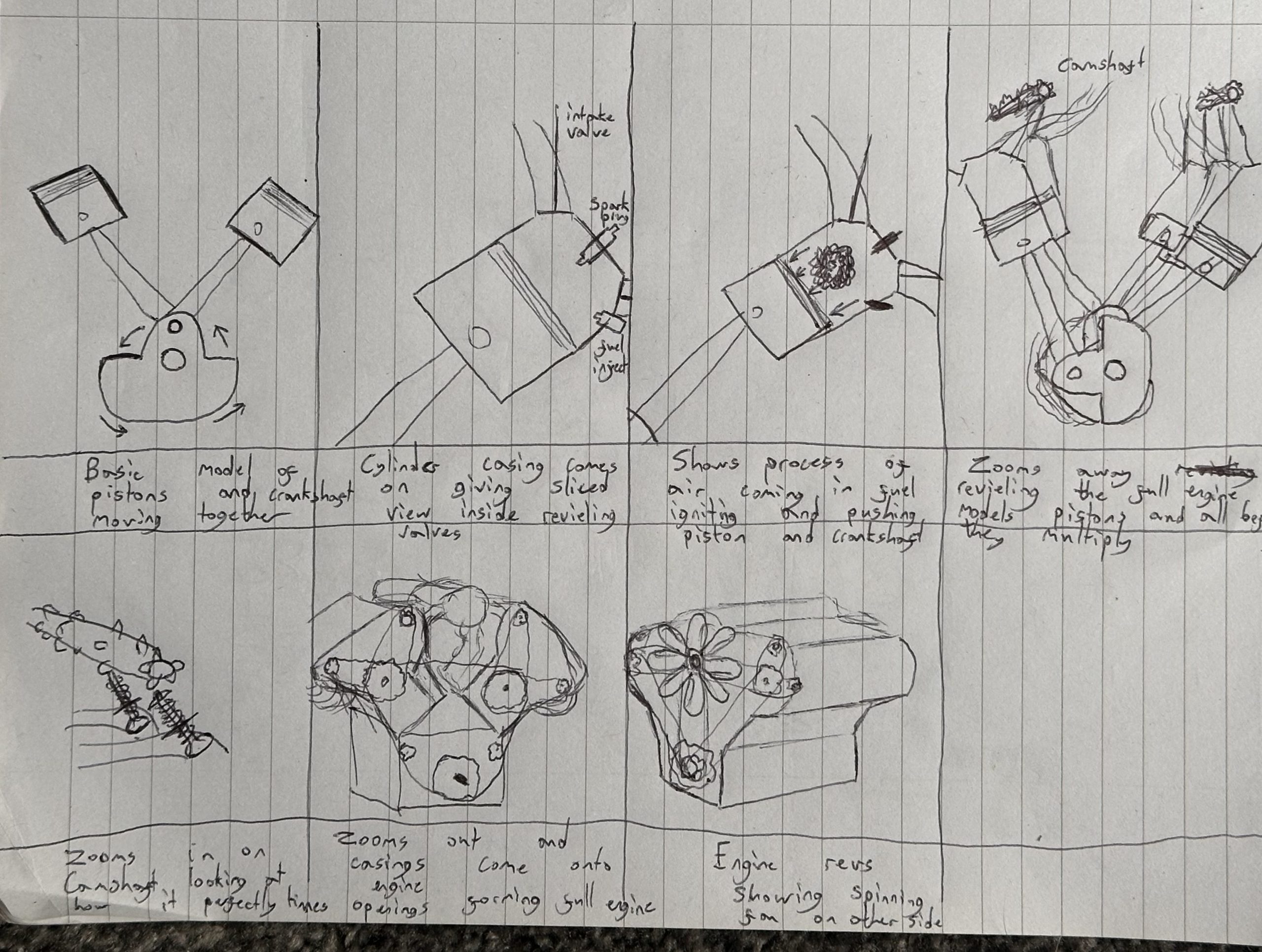
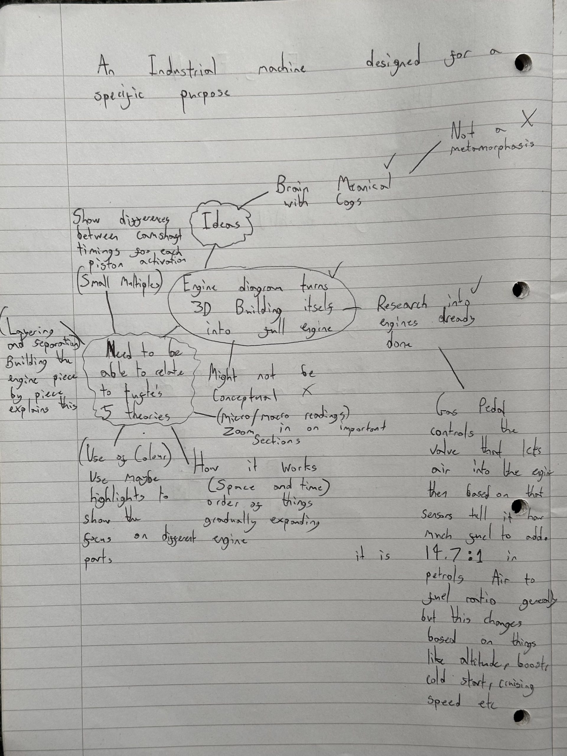
My Initial idea started as a brain made of mechanical cogs however after a bit of thought this didn’t seem feasible or purposeful not matching the brief for the assignment. My next idea was Building on my passion for cars by doing an animation relating to an engine, however i needed to incorporate a transition, which proved harder than i thought. I eventually decided to go with the idea of a diagram turning into a 3D engine, morphing from a 2D labeled diagram into a moving functioning engine in the 3D space.
Conceptual Design
Conceptually this idea is sound however it was initially unclear as to how this could combine two ideas to create a new idea but then it hit me, the actual combining of the 3D and 2D diagrams create a clearer comprehensive picture of how things work than you would get from just one or the other, together they demonstrate the shift from theoretical to practical.
1) Admin (2023)
My Engine Research
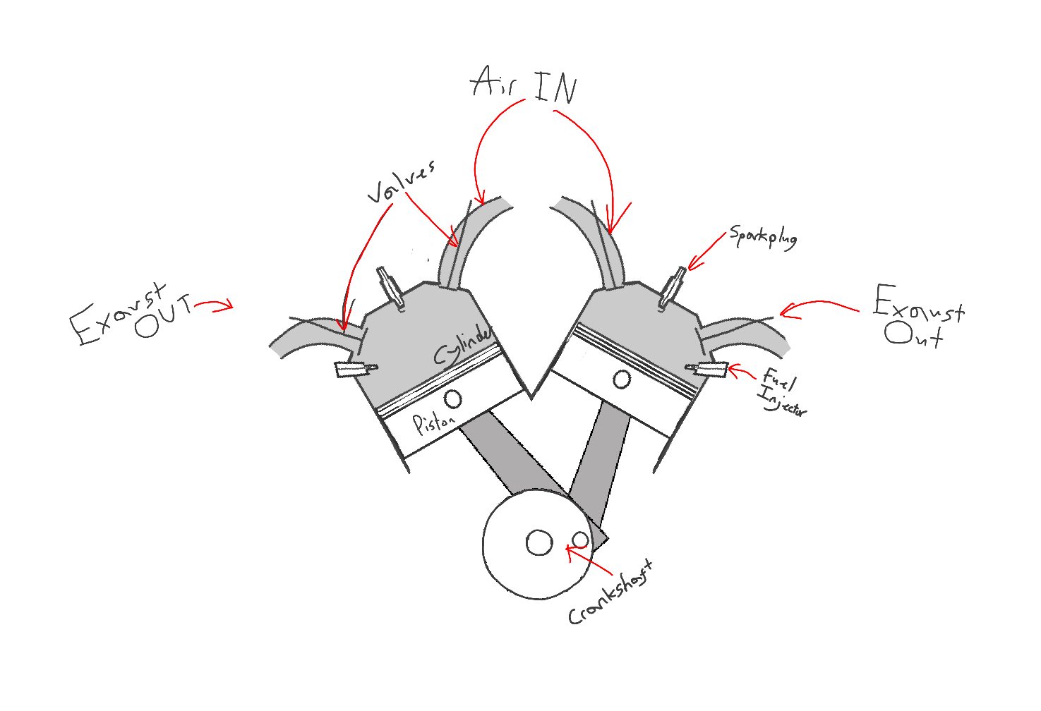
Having a good basic knowledge of engines and how they work before this assignment id placed myself in a healthy position to complete this assignment, however further research was still done in order to expand my knowledge of the subject further and allow me to make a slightly more accurate demonstration of how it should move, what pushes what and what causes speeding up and slowing down.
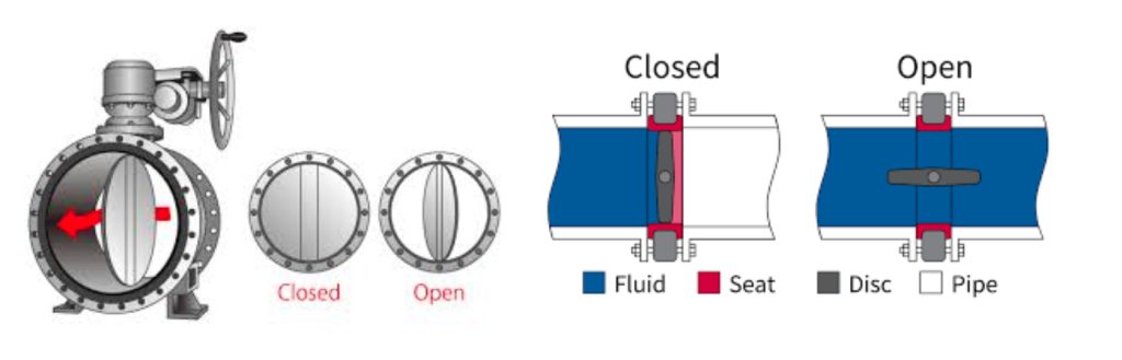
After some research, I found that the valves are what the accelerator controls whether it be physically via a cable in older cars or electronically the pedal tells the butterfly valve to increase the amount of air it lets into the engine and in turn tells the engine to inject more fuel into the mix to get the correct fuel to air ratio creating a more powerful explosion which pushes the pistons and crankshaft to move faster and go up and down more often driving the power to the drive wheels through a gearbox.
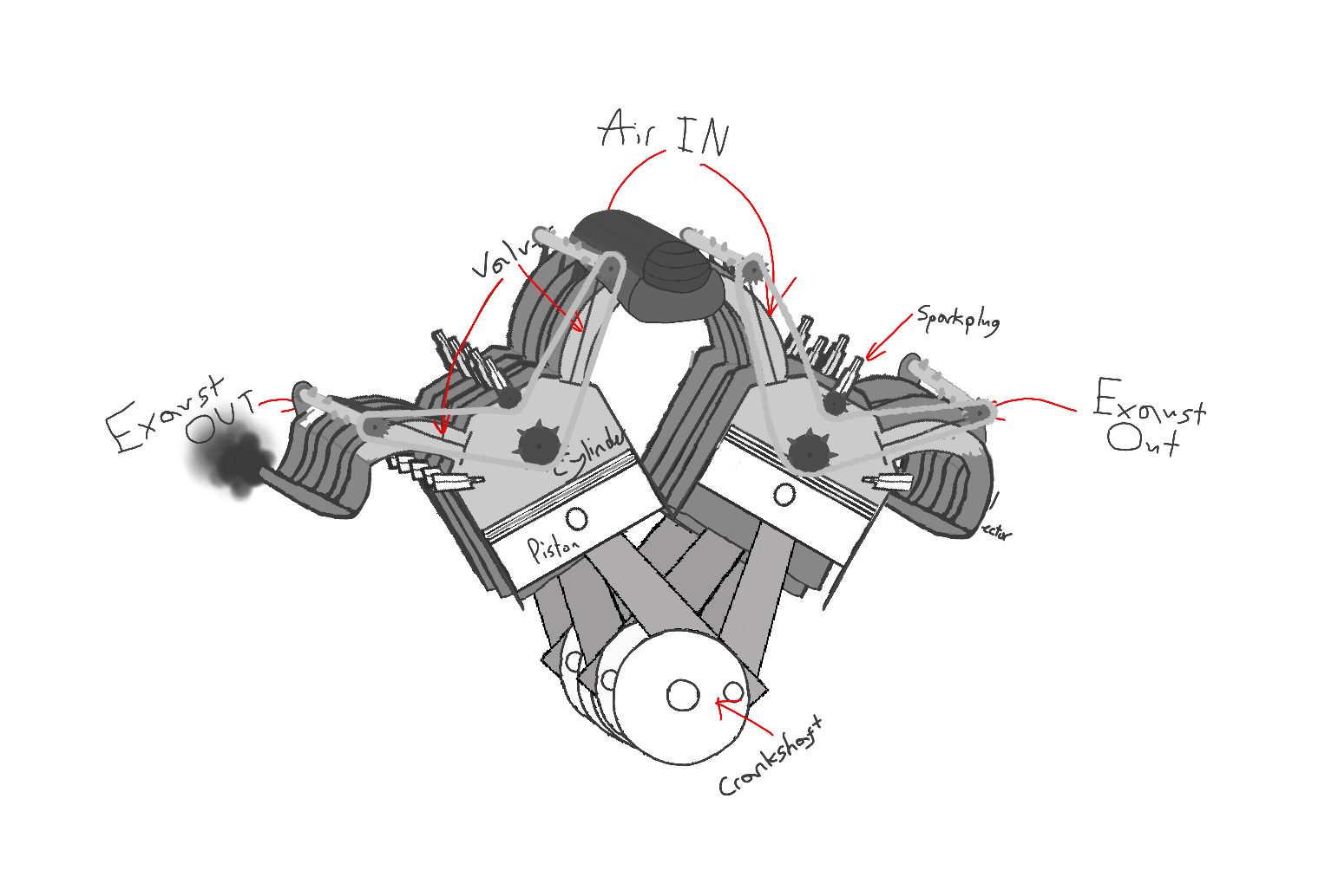
The valves above the pistons get pushed down by the camshaft at the correct times in order for the intake of air and fuel where one side is open, the compression and spark creating the explosion where all valves are closed and upon the next rotation of the piston the exhaust valves are open allowing the fumes to be pushed out by the piston which starts the cycle again. The camshafts that control these movements of valves are connected to the output of the engine therefore will always speed up and slow down with the engine allowing for the engine to run smoothly.
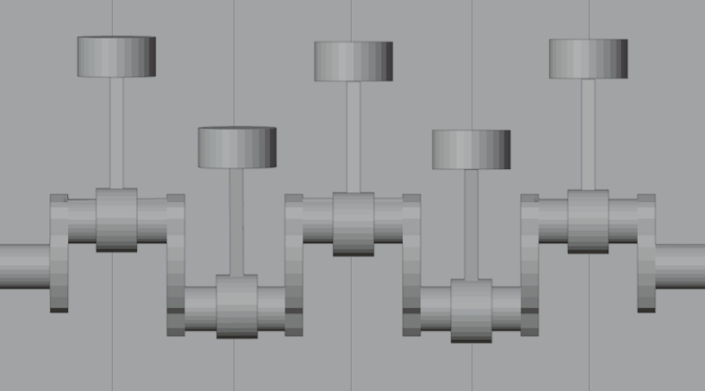
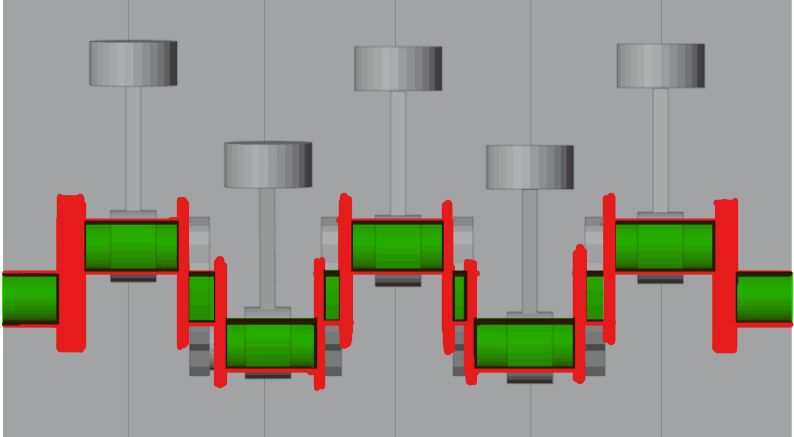
After additional research at the end stages of this project I found a flaw in my design that I now realise would, in reality create a mechanical failure. Unfortunately I found this later on in the project after finalising the design, however being that the brief states the industrial machine can be real or imaginary Im going to ignore this in favour of the idea that my design would be made of a stronger material than a normal engine. The flaw Is that the crankshaft I designed has no central connecting points between the turning points that the pistons connect to, this in reality would cause the crankshaft to bend creating many problems for the engine however if the material was strong enough to not bend at speed this would not be an issue. If i were to do this project again i would learn from my mistake and shape the crankshaft accordingly.
References
Admin (2023) How does resilient seated butterfly valve work?, How Does Resilient Seated Butterfly Valve Work? Available at: https://www.xhval.com/how-does-butterfly-valve-work/ (Accessed: 02 May 2024).
Animagraffs (2021) How A car engine works. Available at: https://www.youtube.com/watch?v=ZQvfHyfgBtA (Accessed: 22 May 2024).